- ORYGINAŁ TYLKO Z ROMBEM
produkty
- strona startowa
- produkty
- i więcej…
- stacje solarne
- Rozdzielacze obiegów grzewczych DN 25/ DN 32

Rozdzielacze obiegów grzewczych DN 25 (LDP)
28. März 2024
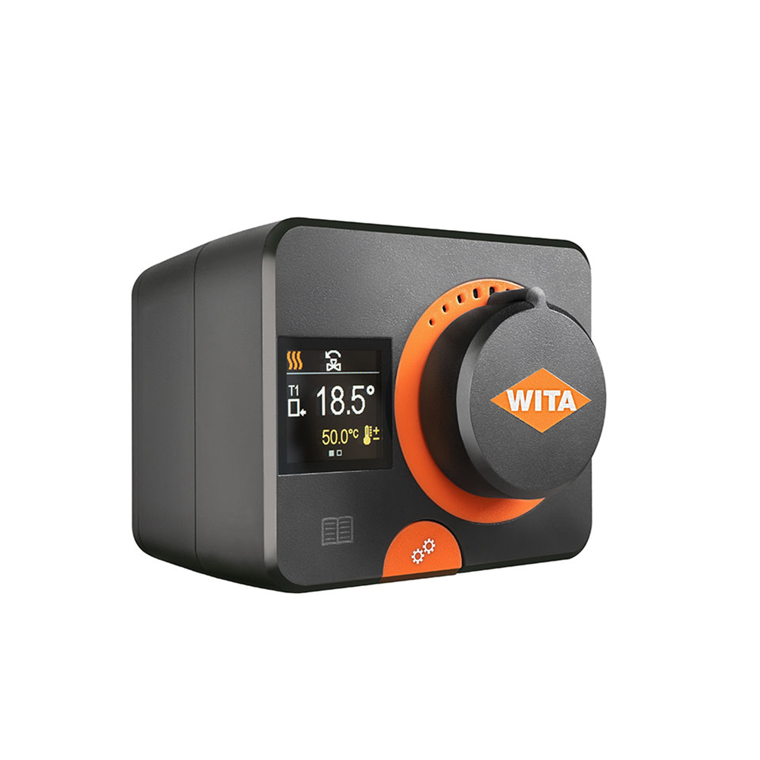
Siłowniki SM Mini KV
28. März 2024Rozdzielacze obiegów grzewczych DN 25/ DN 32
The DN25 and DN32 heating circuit manifolds are used for space-saving and rapid installation
of the heating circuit system. After connecting the heat generator, up to seven heating circuits
(direct, mixed) can be installed on the manifold with a flat seal, depending on the manifold
design. The manifold is used for heating systems up to 110kW/270kW heat load. The manifold is
supplied with an adjustable wall bracket and screw connection for convenient wall mounting.
Kategorie: i więcej…, rozdzielacze obiegów grzewczych, stacje solarne
| DN 25 | DN 32 | |
| Średnica nominalna | DN 25 | DN 32 |
| Wymiary połączenia | 1 ½“ Rp | thermo-tap side top – 2“ Rp
producer side bottom 1 ½“ G |
| Odległość między środkiem obiegu grzewczego i zwrotnego | 125 mm | 125 mm |
| Wymiary (wys. x szer. x dł.) |
2+0, 2+1: 190 mm x 160 mm x 500mm 3+0, 3+2: 190 mm x 160 mm x 750 mm 4+0, 4+3: 190 mm x 160 mm x 1000 mm |
2+0, 2+1: 190 mm x 160 mm x 500 mm 3+0, 3+1: 190 mm x 160 mm x 750 mm 4+0, 4+1: 190 mm x 160 mm x 1000 mm |
| Materiały | EPP, mosiądz, stal, uszczelki, EPDM | EPP, mosiądz, stal, uszczelki, EPDM |
| Zakres zastosowania | 110 kW, do 110 °C, Kvs 13 m³/h, 110kW |
270 kW, do110 °C, Kvs 29.3 m³/h |
| Ciśnienie robocze | maks. 6 bar | maks. 10 bar |


